Constructing the SFS box, Part 3
This update is going to bounce around a bit – I’m presenting the pictures in the order in which they were taken…
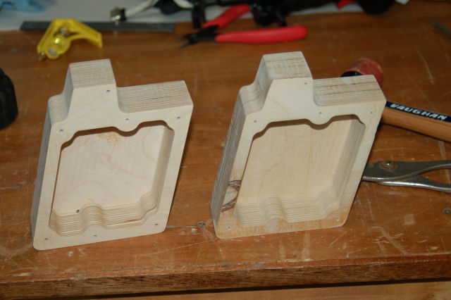
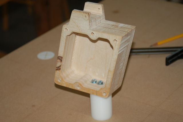
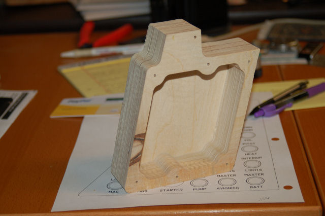
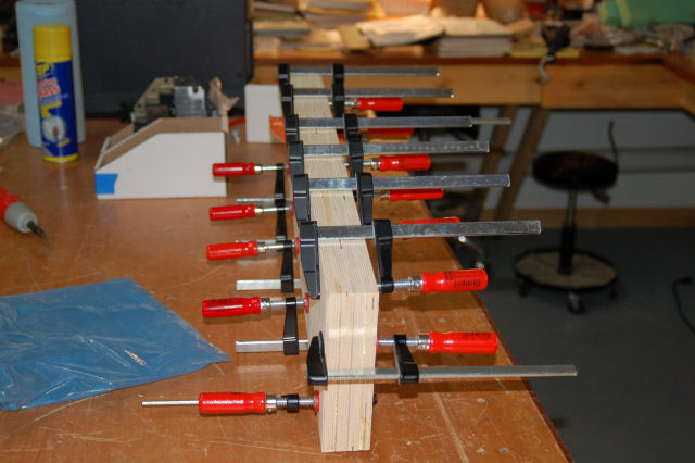
Here are the two SFS box shells right off the ShopBot:
Each one as mentioned before is made from four layers of 1/2″ Baltic Birch plywood.
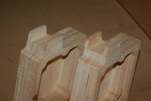
Space cut out for the Nose Wheel Steering and Auto Pilot disconnect paddle:
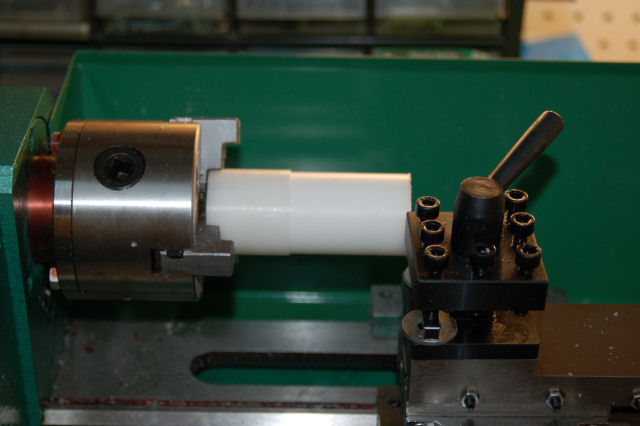
The “real” SFS box is a one piece casting that includes a 2″ mounting post that fits into the stick base in the cockpit. For this version, I had to turn my own post:
The post blank is a 4″ long section of 1.5″ diameter Delrin. Delrin is a very easy to machine material and is quite strong.
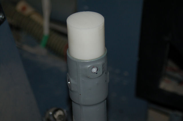
After turning it down to 1.4375″, it’s time to see if it fits…
Insert Happy Dance Here. 🙂
I then cut it down to the 2″ length needed and then drilled & tapped it for 3 #10-24 screws.
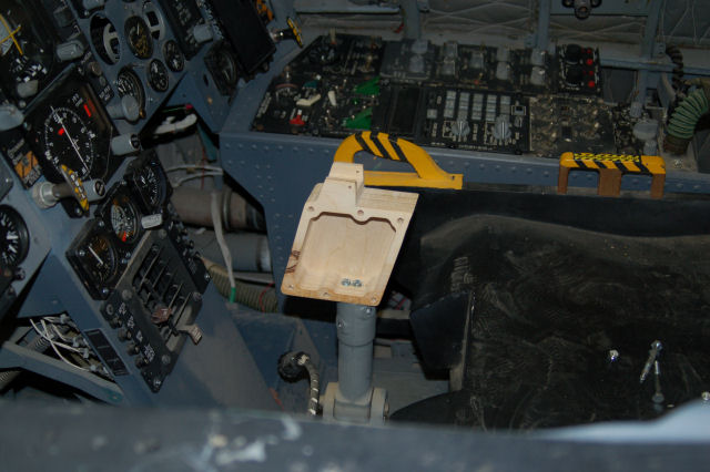
…and just one more test fit…
One word. Muahahahahahahaha!
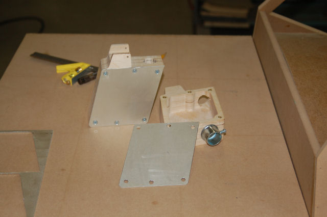
The box sides came next. The sides are .062″ aluminum and I’m using #8-32 brass inserts to allow me to use machine screws with the plywood.
The box to the right is the one that will be in the ‘109F/X.
On a completely unrelated note…
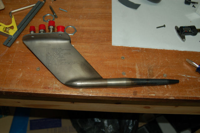
For the poor girl in danger of loosing her Chick License:
Enjoy! *laughs*
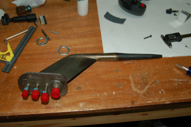
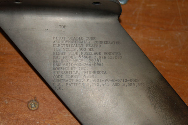
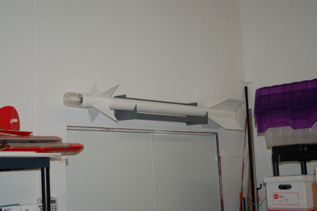
BTW, I do need to find a left-hand pitot tube. This one is for the right side only. 🙂
Thanks for reading!
Constructing the SFS box, Part 2.5
I went to my local acrylic monger yesterday and was captivated by this huge block of gray UHMW. It was _begging_ to become an SFS box.
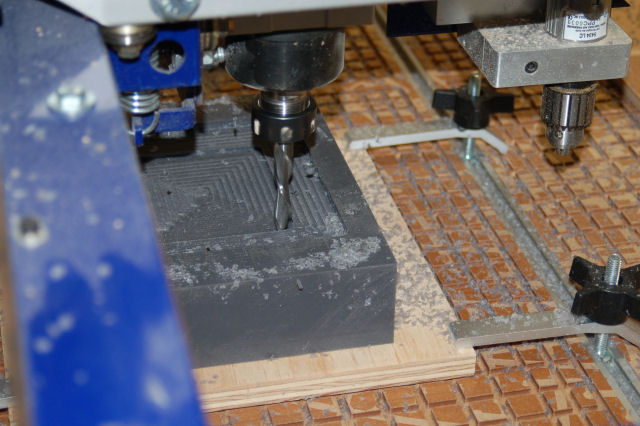
The block was about 10 inches long, 8 inches wide and 2.5 inches thick. I needed to pare it down to 1.75″ thick first…
You can see the UHMW chips flying away from the cutter. I’m using a .50″ downshear cutter running at 12,000 RPM with a feed rate of 1.7in/sec. That cutter is an _animal_ in this stuff. I’ve never cut UHMW before and it was definately an experience I won’t soon forget. I’ll be cleaning up little bits of gray plastic swarf for the rest of my life I think.
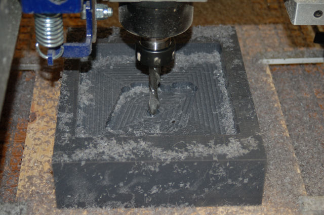
Now we get on to the interior of the SFS box…
All during the cutting process, I was trying to suck up as much of the swarf as I could with a narrow shop-vac hose. The best I could do is keep the stuff from clogging the cutter…
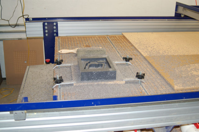
All done! What a f*cking mess. *sigh* The block of material has been glued down to a sheet of scrap plywood with 3M 77 spray adhesive. Worked great!
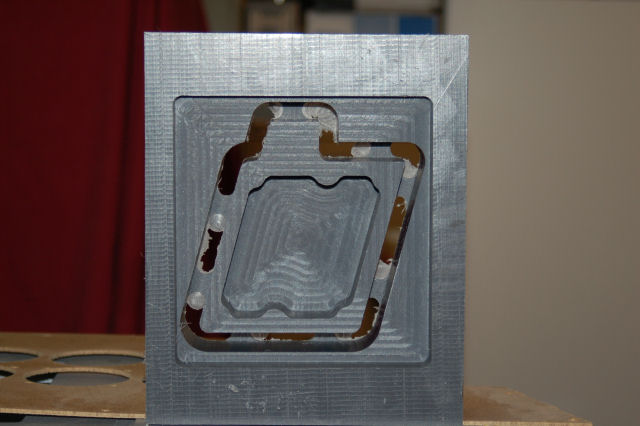
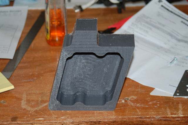
Here’s the end results:
I really don’t care for the finish the cutter left on the box so this will likely be just a fun paper weight. Tomorrow I’ll get the .062″ aluminum cover plates made…
A minor interlude…
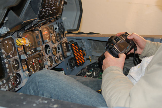
Yesterday (19Dec09) I had the privilege of working with an independent filmmaker. The beginning scenes in the movie involve a couple of guys in dire straights after their F-15D suffers a catastrophic engine failure. He was lucky enough to get access to an F-15D that he could use to film the actors, but he still needed to see the correct emergency lights going off and some shots of “switch magic” where the fire supression system is activated and the relevant warnings appear on the Master Caution panel.
Here’s a picture of the Master Caution panel in “test”:
This is the first time the MCP has been illuminated while installed in the cockpit. There are 74 24v lamps in that panel and it got pretty hot for the 10 minutes or so I ran it so he could get static shots of it. HD video was also taken.
On the SFS front, I managed to ruin two blanks when they moved while being machined. 🙁 I had to lay up two new blanks and wait another 24 hours.
Until next time!
Constructing the SFS Box, Part 2
Today I cut the first SFS box core on the ShopBot:
I went ahead and deleted the additional pocket operation that would have inset the aluminum box cover. Now it will more accurately reflect the original part.
A little bit of finish work will be required to correct the bottom edge profiles where the AP/NWS disconnect lever is mounted.
Part 3, coming soon!
Constructing the SFS Box, Part 1
The F-15 uses a very interesting system for the roll and pitch control – it’s both Fly by Wire and mechanical interconnect.
If you were to pin the stick in place with your knees, you can fly the jet by pressure on the grip all by itself, just like an F-16.
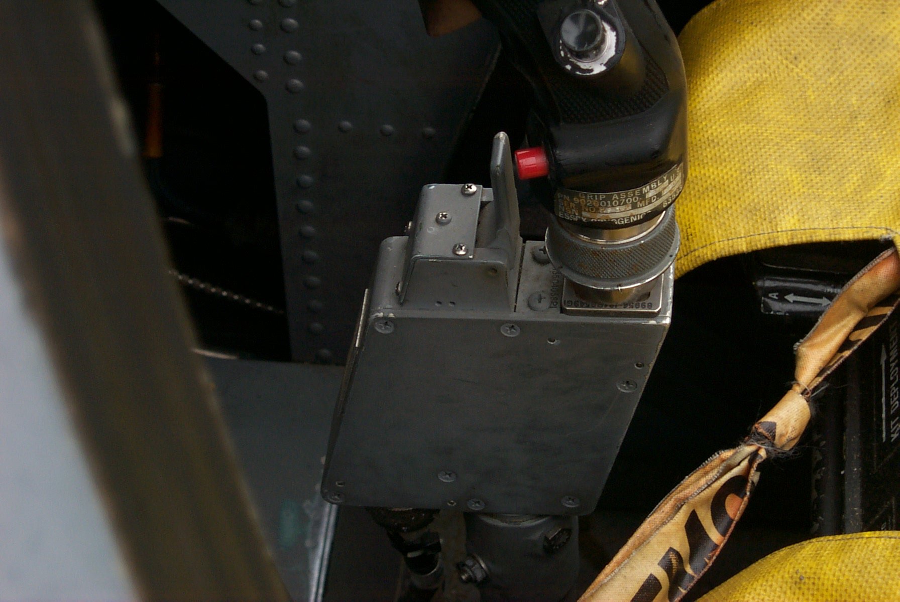
The magic for this happens in the little box that the stick grip attaches to. This box is known as a Stick Force Sensor:
This box holds a load cell beam, very similar to the one in the base that the flight grip of the F-16 plugs into. This load cell is what translates the stick force into electrical signals that the on-board computer translates into control surface movement.
The lever in front of the grip base is the Auto Pilot/Nosewheel Steering disconnect. If you’re on the ground, it disengages nose wheel steering – the red button in the picture next to the lever engages the nose wheel steering. If you’re in the air, the lever will disengage the autopilot.
Because of how important this little box is to my project, I’ve probably got more dimension data than any other part in the whole cockpit.
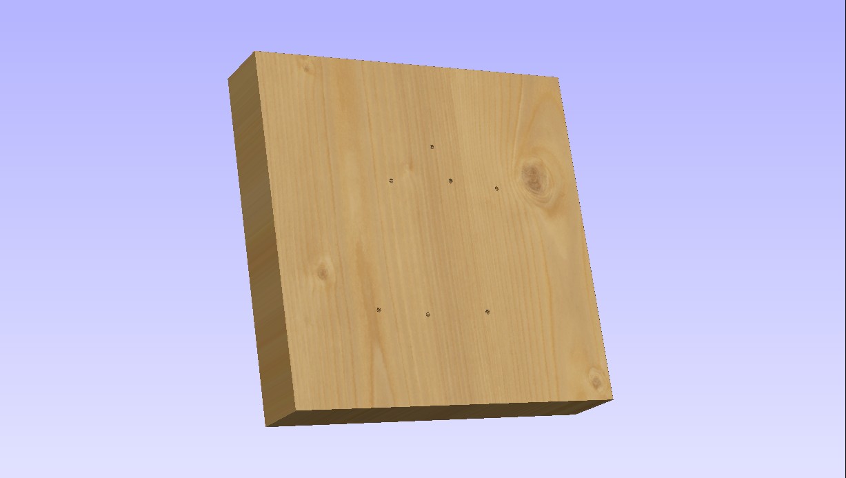
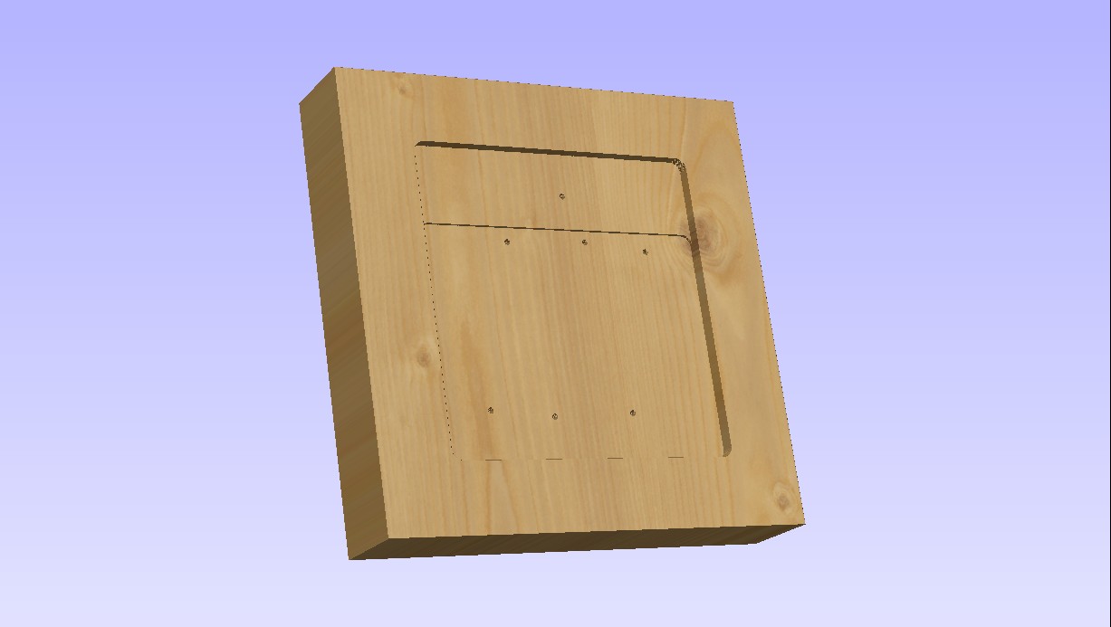
This week I’ll be making one on the ShopBot. The following images are renderings from the software that I use for creating tool paths for parts to be cut on the ShopBot. The base material is a 10″ x 10″ laminated plywood block, 2″ thick.
First up, the drill holes:
Six mounting holes and the hole for the hinge pin for the AP/NWS disconnect lever.
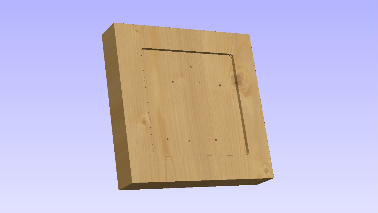
Now it gets machined down to 1.75″ thick:
Now it gets cut down a bit more to make room for the .062″ thick aluminum box cover:
This will result in a different look to the SFS box and I may change it before I cut material.
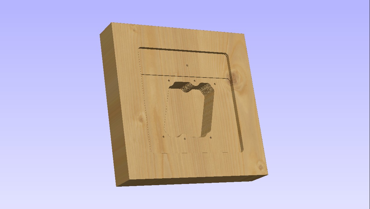
Now we create the main interior pocket for the box:
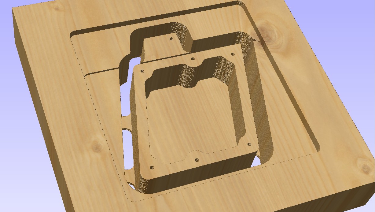
…and finally it’s time to cut the box shape out:
The tabs hold the box into the base material so it won’t shift during cutting. The box will be complete after the sides of the AP/NWS area are shaped to more closely resemble the original.
All the cutting will be done with a .50″ downshear end mill with a 1.75″ cutter length. (The tool itself is 4″ long)
Working towards the SFS
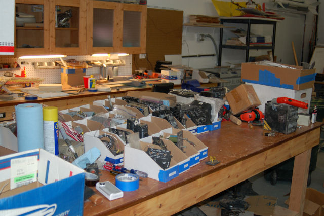
Today I finished hunting down the missing 5 1″ oil & hydraulic instruments I couldn’t find last weekend. Of course, they showed up in the last box I could search.
Here’s the result of my search & sorting operation:
The design for the Stick Force Sensor box is completed. The SFS box is just about 1.75″ thick. Because I didn’t want to build it from acrylic or a block of aluminum, I needed to laminate four layers of 1/2″ Baltic Birch plywood together. This will give me a raw material thickness of a little more than 1.9″.
The block is 24″ long and 8″ wide. This will give me enough raw material to build two SFS boxes. One will go into the F-15 and one will go into my Me-109E/X cockpit.
I’ve got some new cutters on order and as soon as they arrive I’ll get the ShopBot to work on making the SFS boxes.
How’s THIS for a fancy light? 🙂
The AWG-20 PACS
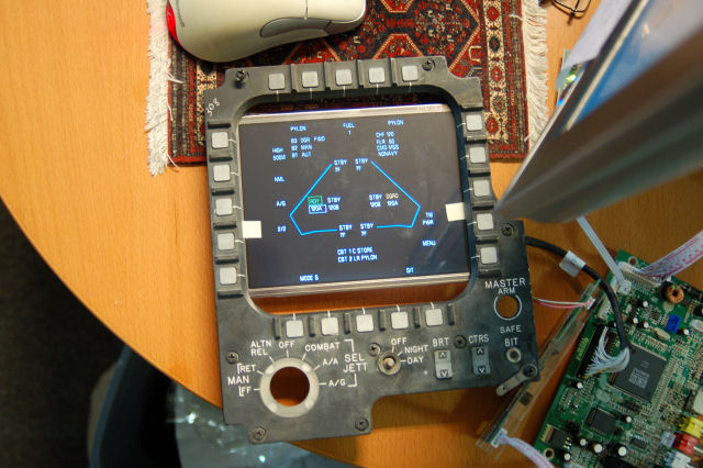
My friend Dave is both a god of both graphics and avian photography. He’ll be writing the software that will show the various screens on the AWG-20 PACS or Programmable Armament Control Set (also known as the MPCD or Multi-Purpose Color Display)
Below is a test display he wrote for me and I’ve put my “spare” MPCD button collar frame around it so you can understand what it’s all about. 🙂
I rebuilt the MPCD that I have with a 7″ monochrome green VGA monitor. Within a couple of months of that feat (it’s not easy shoe-horning a “standard” CRT into the original enclosure!) I discovered that the MPCD is a COLOR display. Cue facepalm.
You cannot buy a 7″ color VGA display for any amount of money. I’ve tried. Repeatedly. For five years. The original display is a 5″x5″ color vector tube and while I could find a replacement, they wanted $5000.00. EACH. Cue 2nd facepalm.
I finally found a 6.4″ LCD kit from Earth LCD to the tune of $350. Painful, but no where near the pain of the original.
So what I’m doing is replacing a 1:1 aspect ratio display with a 4:3 aspect ratio display that “mostly” fits. The important part of the real estate that the LCD covers is the 20 buttons that surround the frame. With a little adjustment, it properly covers all the space that they “occupy” on the screen. I’m going to place a layer of 1/16″ or 1/8″ smoked plexiglass between the LCD and the MPCD button collar. When the unit is enclosed, no light will enter from the back and you won’t notice there’s a huge air gap above and below the LCD.
The original display had a resolution of 512×512. At 640×480, I’ll have the width I need, but I’ll be short 32 pixels (shy 16 at the top and 16 at the bottom for all practical purposes). This will make things a bit tight – there are some MPCD pages that are pretty dense, but I’m sure we’ll get it figured out.
All the bits so far…
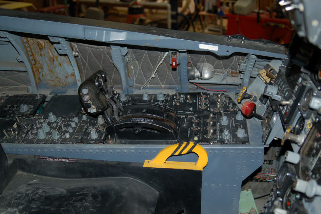
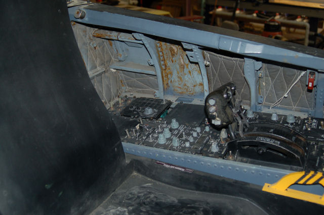
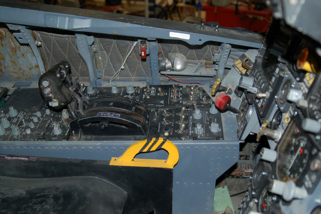
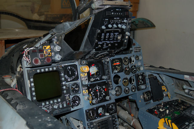
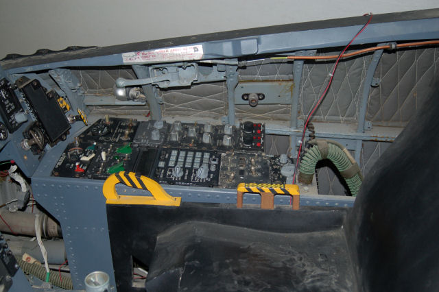
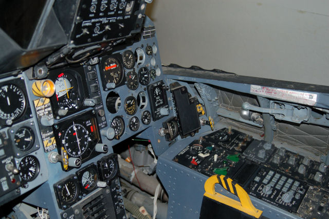
Here’s a set of pictures that show everything that I have (minus some parts I can find!) installed in the cockpit.
The glare shields are not installed, nor is the windscreen in place..
Enjoy! 🙂


