

My original gauge controller boards were done in Eagle, long before Autodesk got their claws into them and murdered them. Fortunately, KiCAD does a pretty good job of importing Eagle projects.
That got me started – I ended up basically redrawing the schematic from scratch, but that was probably the better choice anyway.
Read moreBack in 2015, I began working on replicas of the Fuel Flow, FTIT, and RPM gauges. The gauge design at the time was based around an air-core motor manufactured by SimCo (specifically, https://www.simcoltd.com/products/coil-bobbin-assemblies)
Air-core motors are frequently used in automotive instrument clusters for things like the speedometer, fuel gauge, etc. The units I had were part of a group-buy that I participated in that was run by a number of F-16 cockpit builders. Air-core motors are similar to synchro resolvers in that they’re driven by a sine/cosine signal. Unfortunately for me, I was unable to work out how to drive the motors silently. While they moved fine, there was a high-pitched tone emitted by the motor, which realistically wasn’t something that could be easily ignored. At the time I lacked the attention span to tackle the problem and figure out what the root cause was.
The gauge design sat idle until around June of 2016. About that time I was able to collect enough attention span to chase down a simpler solution to the problem. Instead of working out why the air-core motors whined like I’d stolen their candy, I just swapped over to Switec stepper motors!
It turns out in the years between the group-buy of air-core motors and when I started actually working with them, a Swiss company named Switec had developed a range of stepper motors specifically designed for use in automotive instrument clusters and other pointer-style gauges. The motors turned out to be a perfect solution to my noise problem. They had the range and resolution I needed, the gear hysteresis was no where near as bad as an R/C airplane servo, and they were inexpensive.
Another bonus turned out to be their low operating current. The coils in a Switec motor only consume 20mA each, making them safe to directly drive off the output pins of an Arduino Nano, and no driver chip was required.
Read moreThis flight simulator involves a number of different power supplies that are used to supply the panel and instrument lighting (5VDC), various indicator lamps (24VDC), the control loading system (24VDC), and the CANBus I/O interfaces and instrument controllers (12VDC). For safety and operational reasons, there’s a need to be able to control what power supply comes online and when. For example, if there isn’t at least one engine running, you don’t need any panel or instrument lighting, and the control loader shouldn’t be powered up unless the simulator software itself is running.
Read moreOne of the final tasks I have to do with the VPForce FFB system I’m using for the F-15’s control loader is to permanently connect the power supply it uses.
Read moreIn March of 2006, a person named Steve reached out to me with the following story:
First I’ll tell you the story of how it was that aircraft 007 was chosen to perform at the airshow at Soesterberg (pronounced Soo-sterberg) AB in the Netherlands. Your aircraft was almost brand new to Bitburg AB. It had arrived from the McDonnell-Douglas factory in St. Louis and had minimal hours on the airframe (about 10) when one of the pilots took it on a cross-country mission to Scandinavia.
Read moreNot exactly F-15 specific (F/A-18 actually…), but I figured the folks that follow my shenannigans would get a kick out of this. A year(ish) ago, I found a LAU-117/A launch rail for sale on Facebook, and before common sense could override the PayPal transaction, I’d bought the stupid thing.
Enjoy the video!
I decided some weeks ago that the existing AC power infrastructure that I’d originally implemented really wasn’t going to do the job. As a result of that decision, I pulled all of the old wiring out and replaced it all with a much neater, safer, and useful configuration.
Check it out in the latest update video:
As I discovered in the last video, I had some flight grip switch problems during the testing of the new control loader.
The Castle Up switch and the “pinky” switch weren’t triggering inputs on the VPForce controller. Today I was able to tear into things and figure out what the issue is.
The good news is that the grip switches & SFS box wiring was ok.
The bad news is I had to remove the SFS cable from the cockpit in order to fix an improperly seated pin. Getting that sucker back into the cockpit took about an hour. 🙂
In order to re-install the cable, I basically nailed it in place using a copper Cleco and used a 1″ impact socket to hold down the half of a nut ring that I had for the installation.
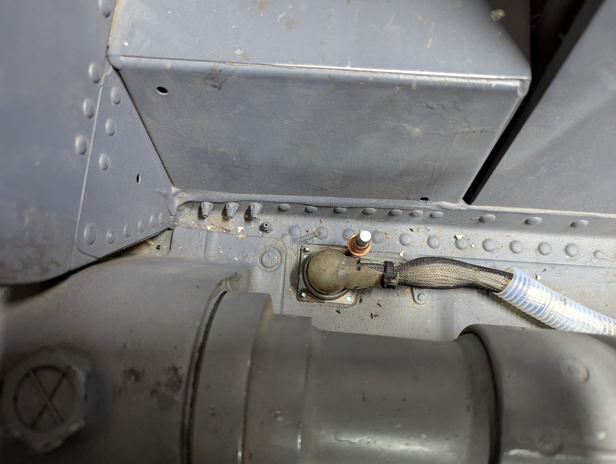
The hard part of this process was threading the #4 screws in from below the cockpit floor while not being able to see the connector, the hole, the screw, OR the screwdriver! It took about an hour of constant fiddling, but I got it done.
I was also able to get the pitch axis tensioner pulley moved inboard the 6mm required so the belt would stop rubbing on the pulley bracket.
Hopefully, more updates next week!
Some months ago I embarked on getting a control loader installed into the F-15C. With flight simulation and air combat “games”, it’s more commonly known as “force feedback”. While the VPForce FFB system I’m using as the base for my simulator *can* do “force feedback” things, the primary task is to provide control loading similar to what a real F-15 pilot would experience. At its most basic level, the flight control system in the F-15 will adjust the amount of force required to move the stick based on the current G loading of the aircraft. The system can require as much as 25lbs in pitch and 20lbs in roll to move the stick at high G loads. The VPForce system can’t quite hit those targets, but it’s close enough for my purposes. I don’t want to become a gym rat just to be able to enjoy my simulator. 🙂
Here’s the YouTube video I put together during the test and configuration of the system. Enjoy!
Before I can get the VPForce-based control loading system installed in the F-15, I needed to build a cable that connects the SFS wiring harness in the cockpit to something that can read the switch inputs from the grip. In this case, that device is the VPForce Shift Register board.
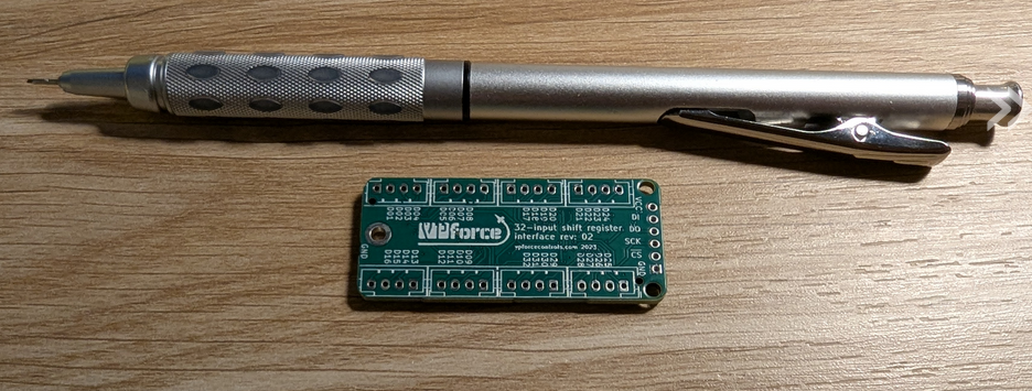
It’s a lot smaller than I expected. 🙂
The SFS (Stick Force Sensor) box is where the flight grip is mounted. It has a post that bolts to the flight stick base in the cockpit. In a real SFS box, the grips mating plug is part of an assembly that contains a load cell. This is where the “Force Sensor” part comes into play.
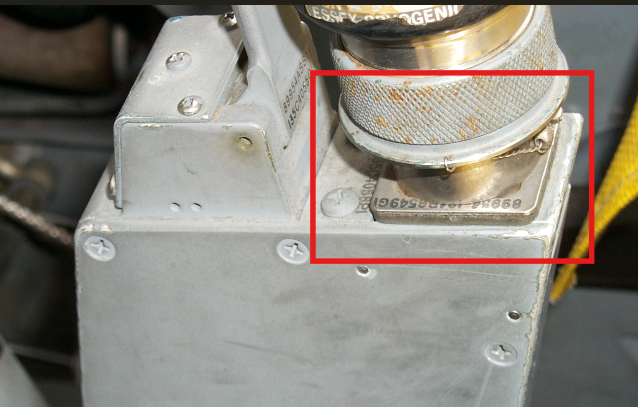
You can see how I built the SFS for this project at this blog entry: https://www.f15sim.com/?p=272
Here’s the video I made that shows how the new SFS interconnect cable was made, and where it was installed. https://www.youtube.com/watch?v=8fHs_51rHa8